
Technical Drawing with Engineering Graphics PDF⁚ An Overview
Technical drawing and engineering graphics are essential for communicating design ideas. These drawings provide geometric specifications for manufacturing components, with detail drawings being crucial for construction. PDF resources, including textbooks and online materials, are readily available for download, aiding in learning the principles and applications.
Technical drawing, often intertwined with engineering graphics, is a fundamental method for conveying precise information about an object or design. These drawings serve as a universal language, transcending spoken and written communication, crucial in fields like mechanical and civil engineering. The discipline encompasses creating detailed, accurate representations of parts, assemblies, and structures, using standardized symbols and conventions. Engineering graphics, as a subset, focuses on the visual representation of technical data, and forms the basis for design communication, and it is the most important course of all studies for an engineering career. Technical drawings are essential for the construction of components and are used to specify the geometry necessary for their creation. The ability to interpret and produce such drawings is a core skill for any engineer, ensuring that design ideas can be accurately translated into reality. They play a vital role in ensuring that designs can be accurately communicated and implemented.
Importance of Engineering Graphics in Design Communication
Engineering graphics plays a pivotal role in design communication, acting as a visual language that facilitates the exchange of technical ideas across different disciplines. It ensures that design concepts are clearly and accurately conveyed, which is crucial for meeting project budgets and time constraints. The clarity provided by engineering graphics avoids ambiguities, thereby improving efficiency and minimizing errors in the design and manufacturing processes. These graphics are an effective tool for communicating technical ideas, and are essential in engineering design where most of the design process occurs. They represent a fundamental tool, with a direct impact on how design teams collaborate. Regardless of their spoken language, people worldwide use technical drawings to communicate their ideas, highlighting the universal nature of this form of graphic representation. Thus, engineering graphics is indispensable for ensuring precise and effective design communication.
Key Concepts in Technical Drawing
Technical drawing involves key concepts like orthographic projections and section views. Dimensioning and tolerancing are crucial for precise manufacturing. The use of CAD software enhances the efficiency of technical drawing processes.
Orthographic Projections and Section Views
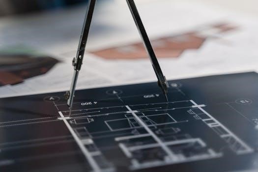
Orthographic projection is a fundamental technique in technical drawing, used to represent a three-dimensional object in two dimensions. It involves creating multiple views of an object, typically the front, top, and side views, each showing a different perspective. These views are projected onto planes that are perpendicular to each other, allowing for a complete understanding of the object’s shape and dimensions. Section views, on the other hand, are used to reveal the internal features of an object. They are created by imagining that a cutting plane has sliced through the object, exposing the internal components. This technique is particularly useful for complex parts with internal cavities or hidden details. Understanding orthographic projections and section views is crucial for accurately interpreting and creating technical drawings, ensuring clear communication in engineering and manufacturing processes. Both techniques are essential to convey complete design information.
Dimensioning and Tolerancing in Technical Drawings
Dimensioning is a critical aspect of technical drawings, providing the precise measurements needed to manufacture components accurately. Dimensions specify the size, shape, and location of features on a drawing, using numerical values and units of measurement. Tolerancing, closely related to dimensioning, defines the permissible variation in dimensions. It acknowledges that manufacturing processes cannot achieve perfect accuracy and sets acceptable limits for deviations from the nominal size. Proper dimensioning and tolerancing are essential to ensure the functionality and interchangeability of parts. Without them, components may not fit together correctly or perform as intended. These specifications are crucial for maintaining quality control in engineering and manufacturing. This process allows for consistent production and reduces errors. A clear understanding of dimensioning and tolerancing is key for engineers and designers when creating technical drawings.
Use of CAD Software in Technical Drawing
CAD, or Computer-Aided Design, software has revolutionized technical drawing, offering a digital alternative to traditional manual drafting methods. CAD programs allow engineers and designers to create precise 2D and 3D models, enhancing efficiency and accuracy. These software tools provide a range of features, such as automated dimensioning, layering, and object manipulation; CAD enables easy modification and revision of designs, which is a significant advantage over manual drawings. Furthermore, CAD software facilitates collaboration through electronic file sharing, allowing multiple team members to work on the same project concurrently. The use of CAD also supports the creation of detailed technical drawings for various industries, including mechanical and civil engineering. This software helps in visualizing complex designs, and it is an essential part of modern engineering practices.
Technical Drawing Standards and Practices
Adhering to industry standards is crucial for creating clear, accurate technical drawings. ISO standards provide guidelines for technical documentation, ensuring consistency and universal understanding across different fields and locations. Best practices promote effective communication.
Overview of ISO Standards in Technical Documentation
ISO standards play a crucial role in ensuring uniformity and clarity in technical drawings across various industries and countries. These standards provide a framework for creating technical documentation that is easily understood by professionals worldwide, regardless of their native language or specific background. ISO standards cover various aspects of technical drawing, including line types, dimensioning rules, symbol usage, and projection methods. They promote consistency in how technical information is presented, reducing the potential for misinterpretations and errors. These standardized practices are especially important in global projects where teams from different regions collaborate on the same design. The application of ISO standards in technical documentation facilitates the seamless exchange of technical data between different organizations, streamlining project workflows and ensuring quality control. By adhering to these globally recognized standards, engineers and designers can produce technical drawings that are both accurate and universally understandable. This adherence ultimately contributes to the overall efficiency and effectiveness of the design and manufacturing processes, as well as improving the quality of final products and constructions.
Best Practices for Creating Clear Technical Drawings
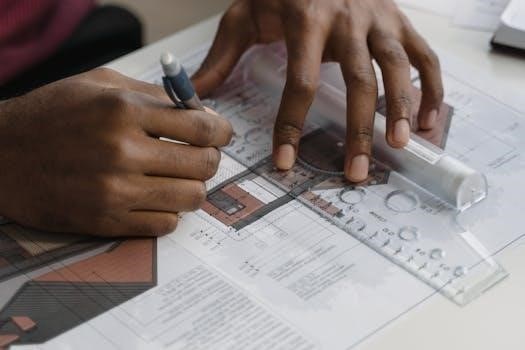
Creating clear technical drawings involves adhering to several best practices to ensure effective communication of design intent. One key practice is using appropriate line weights and types to distinguish between different features of a design. Visible lines should be bolder than hidden lines, and center lines should be distinct from both. Proper dimensioning, using standard practices and clear placement, is crucial for conveying precise measurements. Avoid overcrowding dimensions and ensure they are easily readable. Use standard symbols and notations consistently throughout the drawing to minimize ambiguity. The use of orthographic projections provides a comprehensive view of the object from different angles. Section views are essential for clarifying internal details, while assembly drawings show how different components fit together. Employing annotations and labels to explain specific features is important. Finally, ensure that the drawing is well-organized, with clear layouts and proper scaling. These practices help guarantee that technical drawings are accurate, understandable, and reliable for all stakeholders involved in the design and manufacturing process, minimizing errors and improving project outcomes.

Resources for Learning Technical Drawing
Numerous resources aid in learning technical drawing, including textbooks and online materials. Free PDF downloads of technical drawing resources, such as the 15th edition of “Technical Drawing with Engineering Graphics,” are also available.
Textbooks and Online Materials
A variety of textbooks and online materials are available for learning technical drawing and engineering graphics. These resources range from comprehensive print texts, like the “Technical Drawing and Engineering Graphics” series, to digital ebooks accessible through major online retailers. Many textbooks offer detailed explanations of creating 2D documentation drawings, along with updates to current industry standards. Online tutorials, often provided by educational institutions or software companies, offer interactive ways to grasp the fundamentals. Furthermore, online platforms may include access to problem sets and exercises that help reinforce learned concepts. These materials are essential for students and professionals aiming to improve their skills in technical documentation. It is important to ensure that resources used are current, covering relevant standards, and provide practical examples to improve understanding, offering both fundamental knowledge and opportunities for advanced learning in technical graphics. These materials often include visual aids and step-by-step guidance.
Free PDF Downloads of Technical Drawing Resources
Many free PDF resources for technical drawing and engineering graphics are available online, which can be a great help for students and professionals alike. Several websites provide free downloads of textbooks and guides, often including popular titles like “Technical Drawing with Engineering Graphics” by Giesecke et al. Such resources can offer comprehensive introductions to the subject, detailing both manual and CAD-based drawing techniques. These free PDFs might also include practice exercises and updated standards information, essential for staying current in the field. Users can find materials covering orthographic projections, section views, dimensioning, and tolerancing. Accessing these free resources provides a cost-effective way to learn and practice technical drawing, allowing individuals to explore different topics and techniques at their own pace. This can include material tailored to specific industries, making it a great resource for many. These PDF downloads are a valuable asset for enhancing understanding and skills in technical documentation.
Applications of Technical Drawings
Technical drawings are used across diverse industries, including mechanical and civil engineering. These drawings communicate designs for manufacturing and construction. They serve as a universal language for technical ideas and documentation.
Technical Drawings in Mechanical Engineering
In mechanical engineering, technical drawings are indispensable for the design and manufacturing of components and machines. These detailed drawings convey precise information about an object’s geometry, materials, and assembly. They are the primary means of communication between engineers, designers, and manufacturers. The use of accurate technical drawings ensures that parts are produced to the correct specifications, enabling efficient assembly and proper function of mechanical systems. These drawings often include orthographic projections, section views, and detailed dimensions, adhering to industry standards like ISO. Furthermore, they facilitate the creation of complex assemblies by providing a clear understanding of how parts fit together. These drawings also play a vital role in the maintenance and repair of mechanical equipment, serving as a reference for part identification and replacement. The ability to interpret and create technical drawings is a fundamental skill for any mechanical engineer, ensuring effective design and manufacturing processes. Software like CAD tools aid in creating and modifying these drawings.
Technical Drawings in Civil Engineering
Technical drawings are crucial in civil engineering for planning, designing, and constructing infrastructure projects. These drawings serve as the primary communication tool for architects, engineers, and construction teams. They detail the precise layouts, dimensions, and materials needed for structures like buildings, bridges, and roads. Site plans, floor plans, elevations, and section views are essential components of these drawings. Civil engineering drawings often include details about foundations, structural elements, and utility systems. Accurate technical drawings ensure that projects are built according to design specifications, minimizing errors and ensuring structural integrity. These drawings also facilitate communication with stakeholders, such as clients and regulatory bodies. Furthermore, they are vital for obtaining building permits and ensuring compliance with safety codes. The use of Computer-Aided Design (CAD) software has revolutionized how civil engineers create and manage these complex drawings. These drawings also aid in project management, providing a detailed roadmap for construction activities, and enabling effective coordination between different teams involved in a project.
Technical Drawings in Various Industries
Technical drawings are indispensable across a wide spectrum of industries, serving as a universal language for conveying intricate design information. In manufacturing, they detail the specifications for producing parts and assemblies, ensuring precise fabrication. The automotive sector relies heavily on technical drawings for designing vehicle components and systems. Aerospace engineering uses them to create complex aircraft and spacecraft designs. The electronics industry employs technical drawings for circuit boards and electronic devices. In the field of architecture, technical drawings outline building plans and structural details. The medical device industry uses technical drawings to design and manufacture equipment and tools. Even in the fashion industry, technical drawings are used for pattern making and garment design. These drawings are also crucial in the oil and gas industry, detailing complex pipeline systems. The use of CAD software has improved the accuracy and speed of creating these vital communication tools, making technical drawings an essential aspect of product development and manufacturing across all these diverse industries and contributing to their respective successes.